Options
Options
Lime Options
The Lime options are shown in the Receive DSP panel.
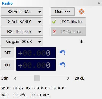
The options are:
- RX Ant: Receive antenna,
- TX Ant: Transmit antenna,
- Vis gain: Visual gain - this value is applied to the data received from the Lime SDR,
- More: Advanced options (below),
- RX Calib: Receive calibration,
- TX Calib: Transmit calibration (radio must be in transmit for calibration to be successful),
- Gains:
- Gain: Set the combined gain value in dB. This function computes and sets the optimal gain values of various amplifiers that are present in the device based on desired gain value in dB. Note actual gain depends on LO frequency and analog LPF configuration, resulting output signal level may be different when those values are changed. When you change this value the LNA, TIA and PGA are updated to reflect the new overall gain setting.
- LNA: Low noise amplifier gain,
- TIA: Transimpedance amplifier setting,
- PGA: Programmable-gain amplifier setting.
The icons:
- 🏡 go to the Lime page (the page you're currently viewing).
- 🡇 show the LNA, TIA and PGA settings.
- 🡅 hide the LNA, TIA and PGA settings.
At the bottom you see the chip temperature, TX drive level and TX peak input since the last update (usually one update per second).
More (Advanced)
Selecting More ...
opens the advanced options display.
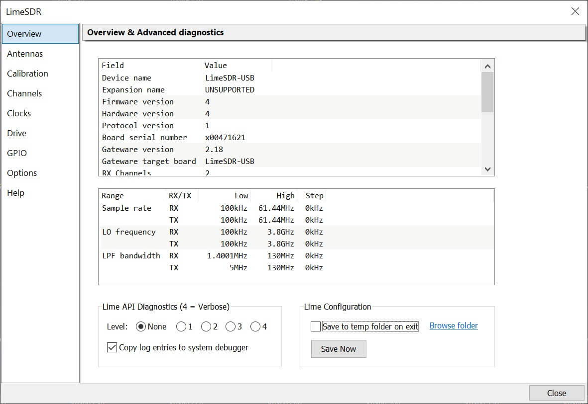
Overview
Shows full information about your Lime hardware and firmware. The Lime support library provides diagnostic information for developers, this can be set to None unless otherwise requested.
Antennas
The Antennas window shows the frequency range assigned to the antennas by the Lime support library, this information does not reflect any hardware changes.
Mini
For the Lime Mini select Auto
for both antennas.
USB
Lime USB you normally select LNAW
for RX and BAND2
for TX.
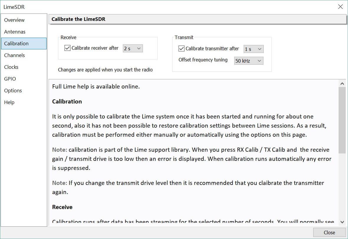
Calibration
Calibration reduces a spur in the centre of the display and strong signal images, both for receive and transmit. It is only possible to calibrate the Lime system once it has been started and running for about one second. Calibration values are restored whenever possible.
Note: calibration is part of the Lime support library. When you press RX Calib / TX Calib and the receive gain / transmit drive is too low then an error is displayed. When calibration runs automatically any error is suppressed.
Spur Reduction
To remove the spur in the centre of the display increase the Gain to ~25dB or more, decrease the Visual Gain (Vis: Gain) to ~-30dB.
Receive
Calibration runs after data has been streaming for the selected number of seconds. You will normally see a small interruption in the waterfall.
Transmit Offset Frequency
To avoid a spur in the centre of the transmission bandwidth, offset tuning is supported. A downside of offset tuning is possible 'ghost' carriers if the transmit calibration has not been run.
Monitoring Your Transmission
The only way to reliably monitor your transmission is with another receiver as there is a lot of leakage between the transmit and receive parts of the Lime chip, so what you see on the waterfall while transmitting may not necessarily be the same signal that is sent to the antenna.
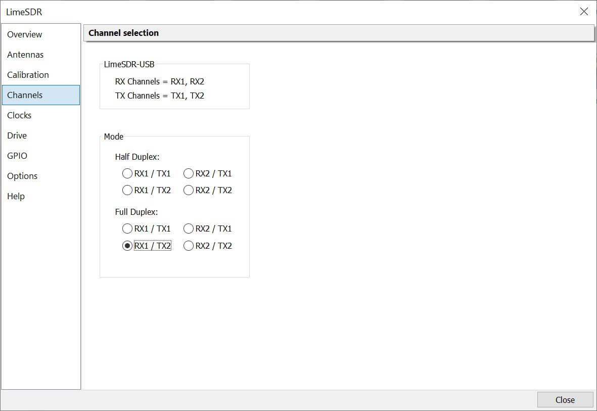
Channels
Select the RX and TX channel used for the Lime USB - for the Lime Mini only RX1/TX1 is available. If using the Lime USB use channel 1 for receive and channel 2 for transmit.
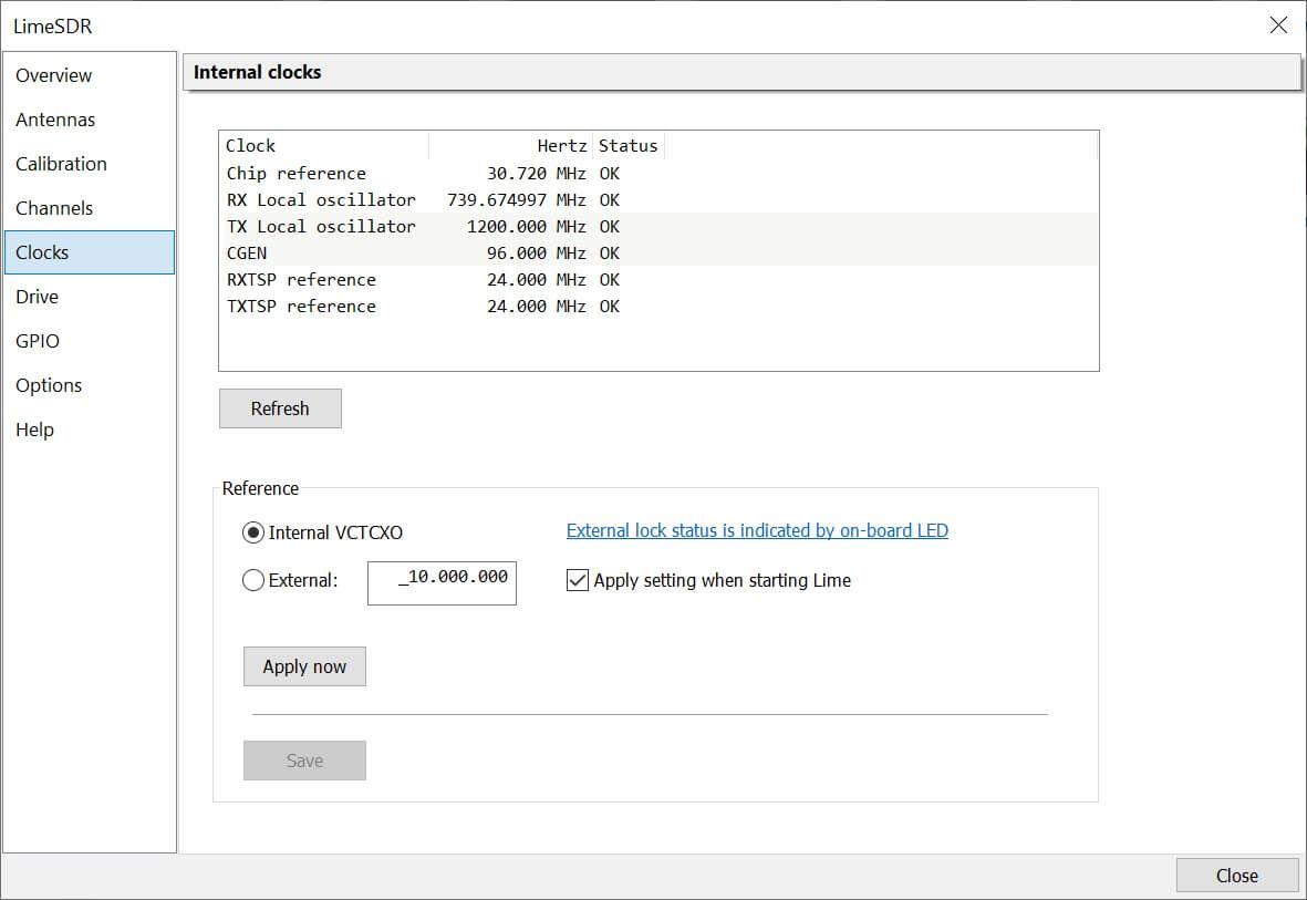
Clocks
Displays the hardware clocks, enables external reference options.
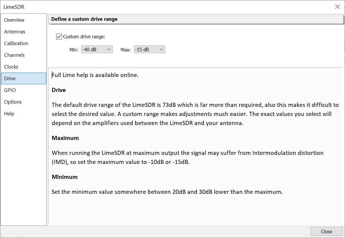
Drive
When the Lime runs at full output power the Intermodulation Distortion (IMD) gets worse, so you must not apply too much drive. The default drive range of the LimeSDR is 73dB which is far more than required, also this makes it difficult to select the desired value. A custom range makes adjustments much easier. The exact values you select will depend on the amplifiers used between the LimeSDR and your antenna.
- Maximum: When running the LimeSDR at maximum output the signal may suffer from Intermodulation distortion (IMD), so set the maximum value to -10dB or -15dB.
- Minimum: Set the minimum value somewhere between 20dB and 30dB lower than the maximum.
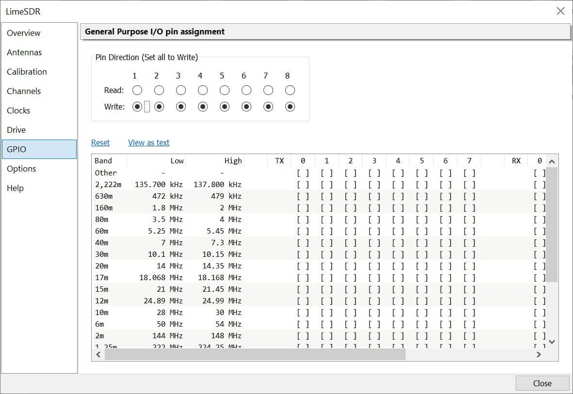
GPIO
Define the General Purpose I/O (GPIO) pins for each band, often used for antenna / amplifier selection.
Options
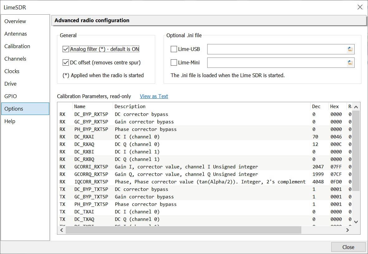
Analog Filters
Enable the analog filters, by default these are enabled (recommended).
DC Correction
To reduce the spur seen in the centre of the display there are two options: Firmware and Software. The software option is usally better than firmware. Gain and Phase correction are usually enabled.
Ini files
Used for development / test purposes, specify a .ini file with pre-defined values. These .ini files are usually created with the limeSuite GUI.